Contact Us
Tel : +86-18668608946
Fax : +86-0717-3902201
Email : aw0024@szautoware.com
Add : West section of Jinping Avenue,Dangyang,Hubei province,China
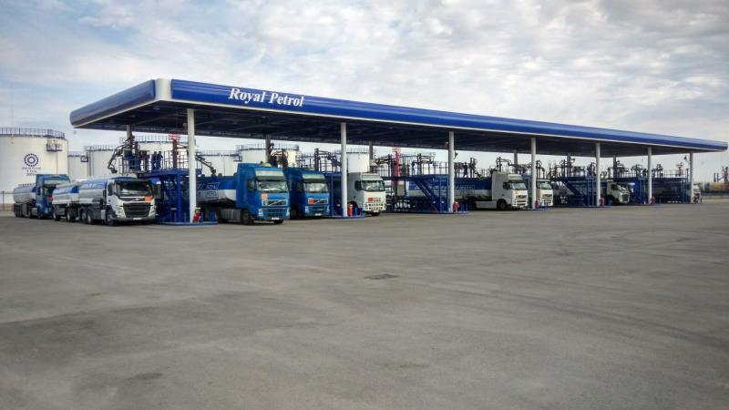
Kazakhstan Royal Petrol Royal Oil Depot SCADA Control System
Project introduction: Hubei Hongyi Electronic&Technology Co., Ltd. actively responds to General Secretary Xi Jinping's call for the Belt and Road, stepping out and “going out”, and has achieved business in many countries and regions such as Central Asia, Africa, Latin America, etc. To achieve mutual development and common prosperity with foreign friends.

In 2016, our company signed the first phase SCADA control system of Kazakhstan Royal Petrol Royal Oil Depot, located in Almaty City, Kazakhstan. The project has a storage capacity of 150,000 cubic meters of gasoline and diesel storage base, a total of 56 storage tanks and 14 sets of quantitative equipment. Car crane position, 20 sets of train loading and unloading cranes, 956 electric control valves, supporting high-pressure pump room area, fire protection system, etc. All instruments and instruments used in the project are supplied by our company, guide installation and wiring, Scada system debugging and final training acceptance. transfer. This project was fully experienced in January 2019. The equipment was used well and the system was running stably. It greatly improved the working conditions of foreign operators, reduced labor intensity and operating costs, and realized the data management of oil products in and out, while ensuring production safety. Improve the operational management level and economic benefits of the reservoir area.

System structure introduction:
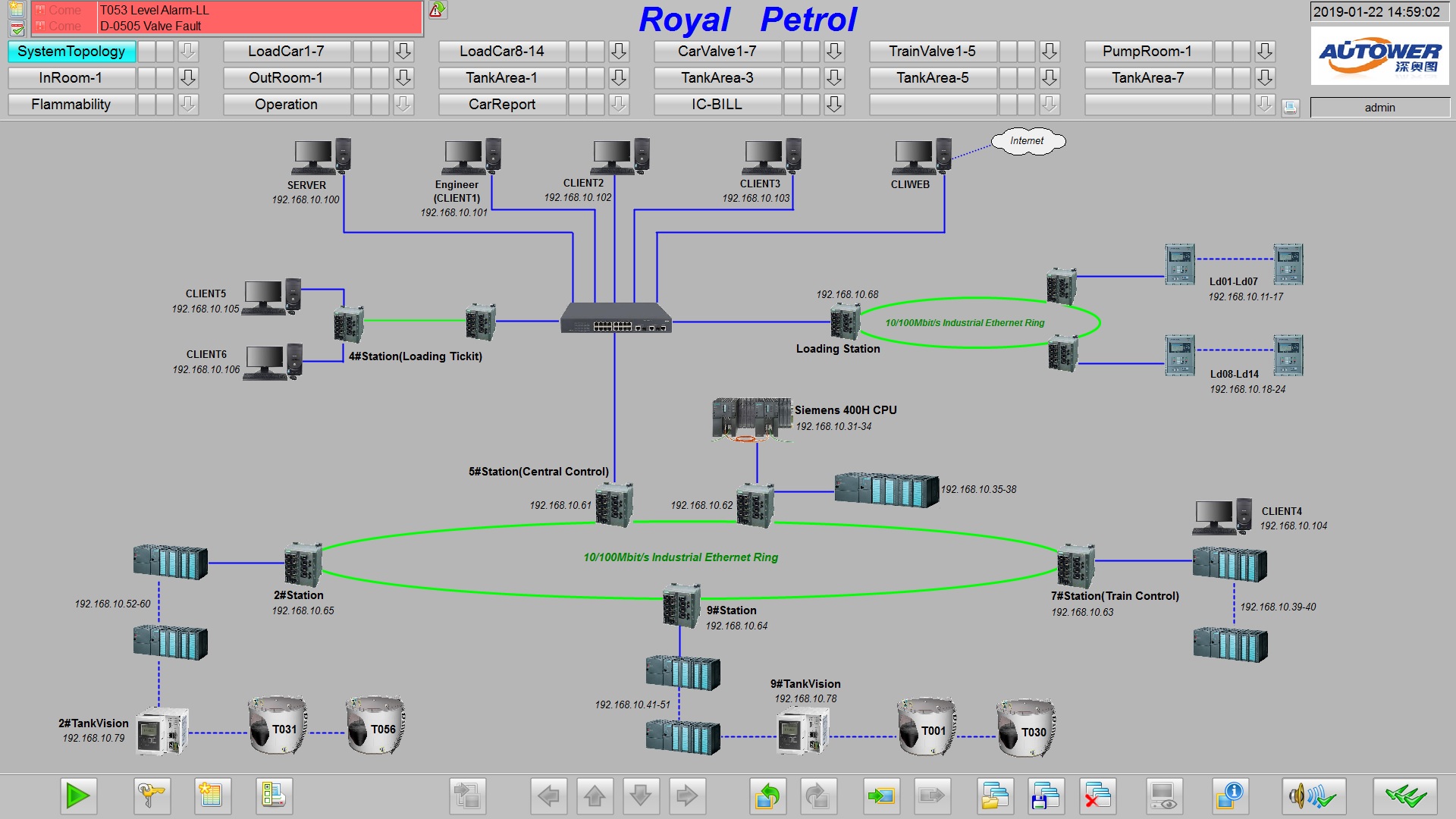
The system is designed with one central control room, four on-site cabinet rooms, one loading control room, and one train unloading control room. There are a total of 26 slave racks, and the total number of physical IO points is close to more than 8,000 points.
The central control room is installed with the host computer system (UPS, computer, printer, main control PLC cabinet);

5# On-site cabinet room installation of electric valve distribution area, variable frequency pump control cabinet, main control PLC cabinet and some PLC I/O cabinets;
7# On-site cabinet room installs some electric valve distribution cabinets and some PLC I/O cabinets in the train loading and unloading area;
9# On-site cabinet room installation of some electric valve distribution cabinets in the train loading and unloading area and tank area, pump room variable frequency pump control cabinet, T001 to T030 storage tank, all instrument power supply and signal, gas detector, tuning fork switch, part PLC I/ O cabinet;

2# On-site cabinet room installation part of electric valve distribution cabinet in tank area, T031 to T056 storage tank all instrument power supply and signal, gas detector, tuning fork switch, part PLC I/O cabinet;
Loading control room installation loading management upper computer system (computer);
Train unloading control room installation loading management upper computer system (computer);
It also provides LAN browsing function for local area network and external network (Internet mapping provided by the owner).
Specifically look at the following figure - network structure diagram and system topology diagram
![1569048312176012.png WR4C50]NGS42$[9M2L7{Y89.png](/static/upload/image/20190921/1569048312176012.png)
Brief introduction to the functions of each structure of the system:
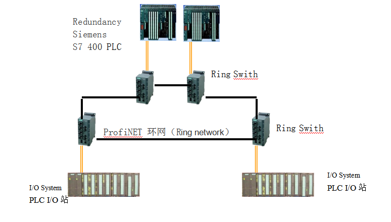
Automatic control system: According to the scale and characteristics of the system project, the PLC control system selects the S7-400 series large PLC of Siemens company. The Siemens S7-400 series PLC has powerful functions, advanced technology, strong expansion capability and strong communication capability. Communication with the field IO slave racks through the redundant fiber ring network Profinet.
The upper computer adopts Wincc configuration software, integrates with PLC for modular development, and is easy to modify, increase and maintain in the online, fully embodying the concept of PCS control system. In addition to the tank area process and data acquisition, monitoring and storage, the system's tight chain logic greatly improves the safety level of the reservoir area. In addition, the canister data publishing function (WEB) is implemented through the Internet, that is, after successfully logging in through the Internet, the online data of the tank area can be browsed remotely.
All templates should pass the safety certification of the authority, including: UL, CSA, CE, etc.;

The system shall be capable of continuous and reliable operation in an industrial environment of electromagnetic interference and vibration. The system hardware can operate continuously and reliably in the temperature range of 0~60°C, humidity 0~95%, altitude 2000m;
The average time between failures of the system is more than 700,000 hours;
All modules in the system should be plug-in and can be plugged in and out. The control system CPU module, power module, I/O module, and communication module support hot plugging and can be inserted into any slot in the rack.
The I/O modules and CPUs of the Siemens redundant system are corresponding to the same level and modules of the same series. The terminals of the I/O modules use the same type of terminal strips.
20% of the total I/O is provided in the cabinet for backup, and there is room for expansion of 20% I/O on the slot.
The configuration and addressing of all I/O modules is implemented in software without jumpers and DIP switches. All I/O modules must have isolation devices and LED module status display units that can withstand voltage surges of ≥1500Vac in one minute.
The S7-400 redundant PLC adopts dual-system hot standby structure, and the CPU module, power module, Ethernet module, and network all adopt redundant configuration. Users do not need to write a switching program to achieve bumpless switching.
The S7-400PLC hot standby CPUs are installed in two independent racks. The hot standby host and the standby unit are connected to each other through a 100Mbps high-speed fiber link integrated in the CPU. This fiber can be expanded to more than 2KM.
Two redundant power modules are inserted in the same rack to meet the requirements for power redundancy.
In the S7-400 hot standby system, the hot standby communication ports are integrated on the CPU. The communication speed between ports is greater than 100Mbps, and the hot standby switching speed is ≤100ms.
If any one site fails, it will not affect the entire network operation.

System chain introduction
The chain of the entire reservoir area mainly controls the chain of cutting devices such as emergency shut-off valves and high and low voltage variable frequency pumps. In order to improve the safety of the reservoir area, 1: When the change of the tank liquid level exceeds the set alarm threshold, the corresponding emergency shut-off valve and high and low voltage lead pump will be immediately shut down or stopped, and the central control room will pop up an alarm message and Departure alarm sound; 2: When the equipment itself fails or the action timeout or the running current is too large, the alarm will be automatically prompted, and the equipment will be stopped immediately. It is in the ESD state. After the manual on-site processing is completed, the alarm state must be manually cancelled. Reset; 3. According to the oil type of each tank, when the tank valve is opened and closed, it will automatically detect and prompt the operator to select the oil type and pressure of the valve line, effectively avoiding the operation of the employee. Mistakes caused oil chaos.
Level measurement system
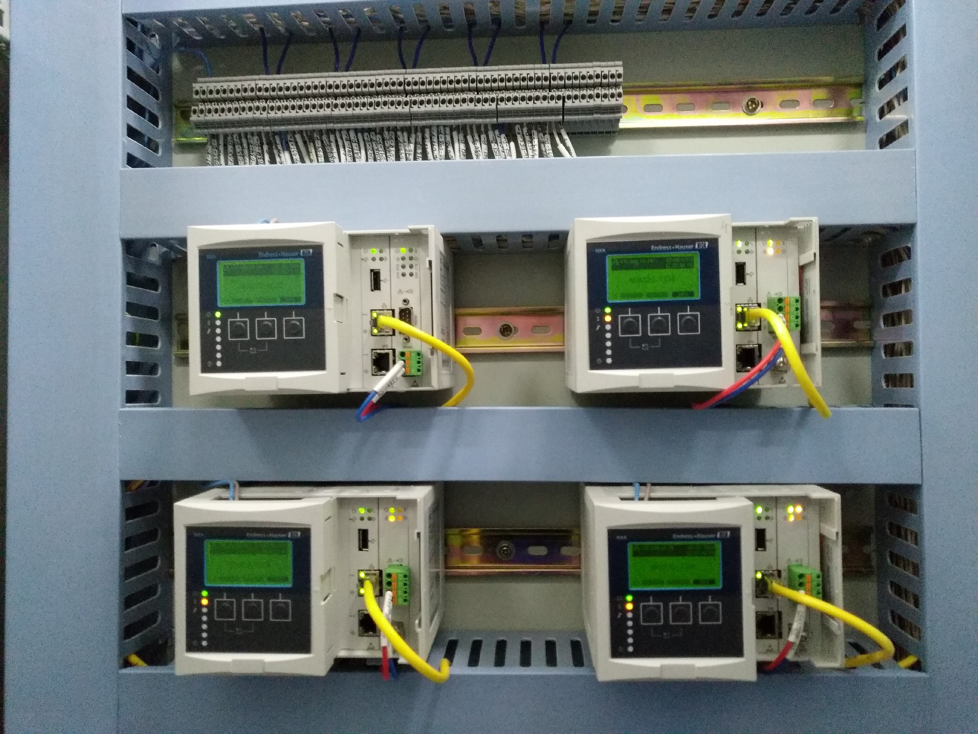
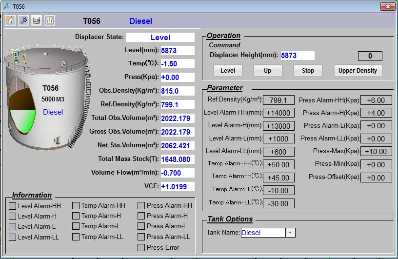
The level gauge uses E+H Endershaus servo level gauge, including average thermometer, vacuum pressure gauge, tank side indicator, and communicates with the automatic control system through the Tankision 820/822 using V1/Modbus. Through the tank capacity table to calculate the total apparent volume, gross volume, net standard volume, inventory quality, inflow and outflow, VCF value of the tank, the operating level of the servo level gauge can be controlled and the real-time density can be measured at any time through the automatic control system.
Loading control system
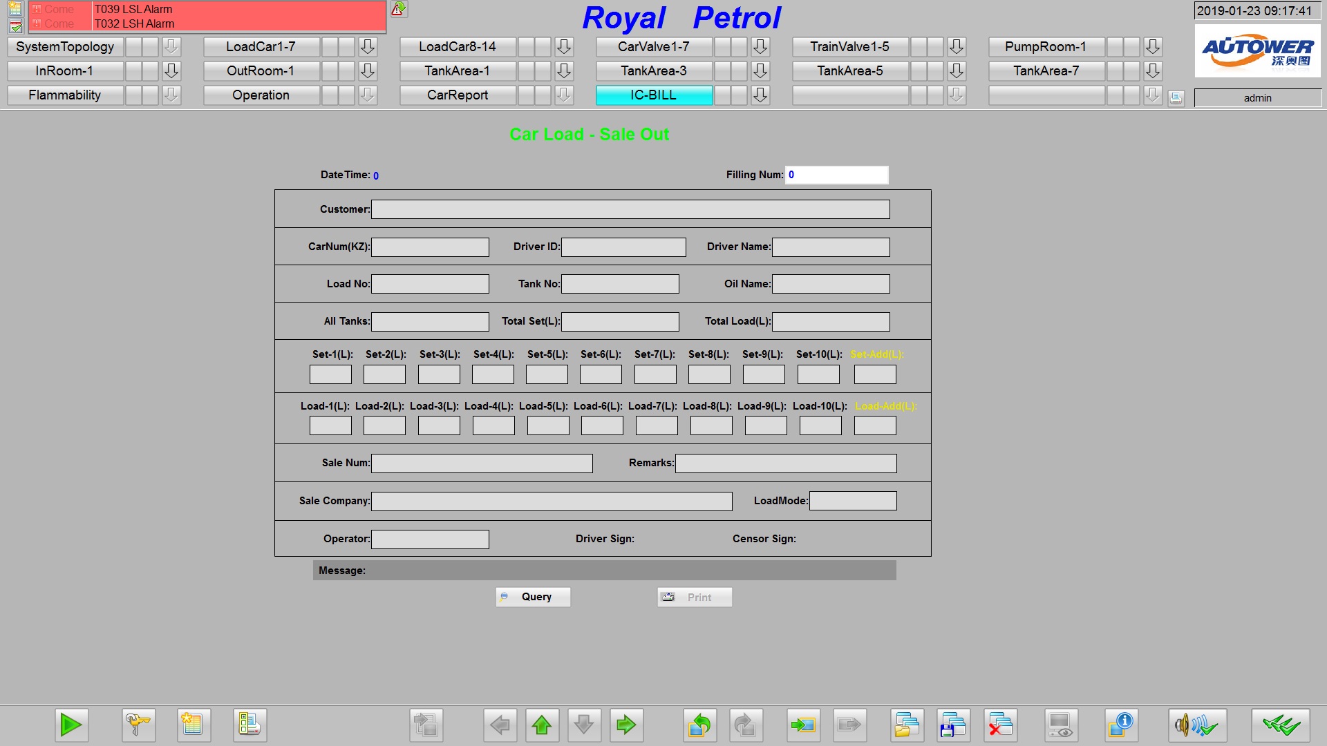
14 sets of distributed quantitative loading controllers, using TCP/IP Ethernet ring network to communicate with the host computer. Regardless of the flow rate and pressure, the loading accuracy is strictly controlled within plus or minus 1L. It is a new intelligent explosion-proof explosion-proof instrument with advanced intelligent controller as the core. Its core components adopt intelligent controllers and operating terminals of world-renowned brands, combined with common industrial control configuration software and advanced control algorithms, featuring high control precision, reliable performance, easy maintenance and use. At the same time, the IC card reader is integrated internally to enhance the loading process management function. The control instrument is a general-purpose product, which can be matched with various flow meters, thermometers, liquid level switches, grounding switches, control valves, and upper-level machines to form a complete distributed quantitative loading control system. The loading instrument can be operated in a single machine, operated and monitored by the operator. It can also be connected to the computer in the control room through the communication cable. The remote loading operation control is realized by the computer, and the on-site loading information is summarized into the control room. Centralized management, display, printing daily reports, monthly reports and other types of loading reports.


 EN
EN
 RU
RU


