Analysis and Comparison of Oil vapor Recovery system processing Technology
1. Activated carbon adsorption method for oil vapor recovery system
The hydrocarbon-containing gas produced during the storage and transportation process passes through the activated carbon adsorbent bed, and the hydrocarbons in it are adsorbed by the adsorbent. The adsorption process is carried out at normal temperature and pressure.After the adsorbent reaches a certain degree of saturation, it undergoes vacuum and decompression regeneration. The oil and gas desorbed during the regeneration process is then absorbed by oil, and the lean gas after absorption is returned to the adsorption process for adsorption.
 The main process units include:Oil and gas collection, adsorption process, regeneration process, compression process, absorption process, heat exchange and sealing.The advantage of the adsorption method is that the concentration of oil and gas in the outlet gas can be controlled by changing the working conditions of adsorption and regeneration.The disadvantage is that the process is complex and the adsorption bed is prone to high temperature hot spots (laboratory tests have proved).Triphenyl is easy to deactivate activated carbon; the treatment of inactivated activated carbon is a problem. There are no domestically-made industrial installations in operation in China, and there are four sets of imported installations in operation in the oil depot, and the cost of equipment purchase is high.
Process flow:The oil and gas generated at the loading location enters the oil vapor recovery unit through the closed loading arm.Before the oil and gas enter the device, it passes through a drain tank to ensure that the oil and gas particles without gasoline enter the carbon bed.In addition, a PVV (Vacuum/Pressure Valve) emergency exit is also provided on the oil and gas main pipe, which can ensure that the device releases the oil and gas in the oil and gas main pipe in a shutdown state.PVV emergency exits or other emergency exits should be equipped with corresponding flame retardant hydrants.
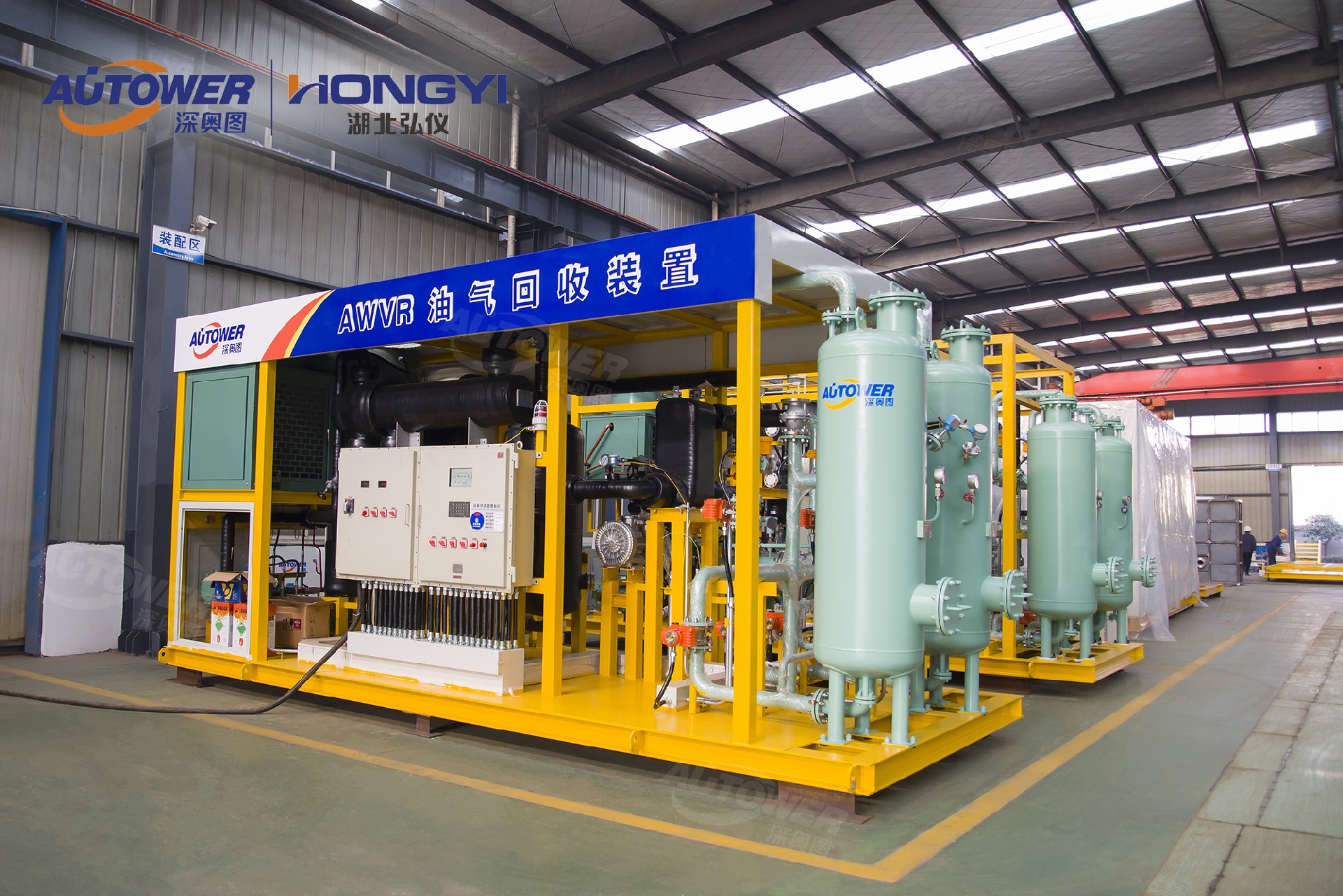 Components:The oil vapor recovery unit is composed of two carbon beds, one is connected to the oil and gas inlet pipe through a valve and is in the "adsorption" state, and the other is "regenerated" through a vacuum pump.The two carbon beds work at the same time to ensure timely recovery and treatment of the oil and gas continuously entering the unit.That is: one carbon bed is used to adsorb hydrocarbons in oil and gas, and the other carbon bed discharges the adsorbed hydrocarbons through a vacuum pump; when the adsorbed hydrocarbons of the first carbon bed reach saturation, it will immediately switch to the "regeneration" operation (ie desorption) Stage), and the first carbon bed that has been emptied before enters the next stage of "adsorption" state.
The regeneration of activated carbon needs to be completed in two stages.First, the activated carbon container is evacuated, and the adsorbed hydrocarbons are separated from the carbon bed, so that most of the hydrocarbons are desorbed.Then, in order to ensure that the hydrocarbons in the carbon bed are removed as thoroughly as possible, it is necessary to introduce a small amount of air to purge the hydrocarbons that may remain on the carbon bed.The vacuum pump used in this device is a liquid ring pump.A liquid-gas separation tank and a heat exchanger are required. The sealing liquid of the vacuum pump is a mixture of ethylene glycol and water. The standard optional medium for heat exchangers is gasoline or other types of condensate.
In the separation tank, high-concentration hydrocarbon gas enters the absorption spray tower. The gasoline drawn from the gasoline storage tank is sprayed from the top of the tower and mixed with bottom-up pure hydrocarbon gas, thereby achieving the absorption of hydrocarbons in the gasoline.
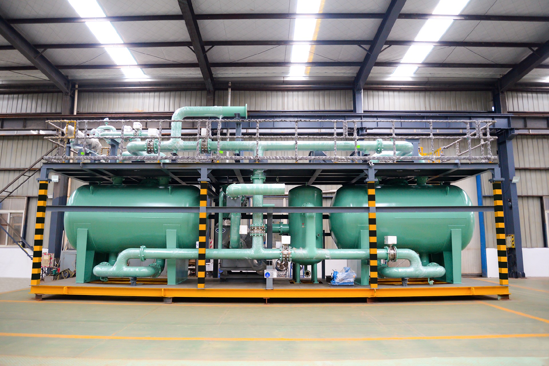 The whole set of devices has an automatic energy saving function: if loading stops, all devices are in standby operation. The device in the standby state can be activated at any time. The vacuum pump is automatically started at regular intervals to keep the carbon bed clean and the activated carbon active. When the next loading starts, the whole set of equipment will start automatically.
Activated carbon adsorption method oil vapor recovery unit is a popular technology in Europe and the United States. Its characteristic is that by changing the operating conditions of the device, the concentration of hydrocarbons in the outlet gas can be controlled to meet different emission standards.
2. Absorption of oil vapor recovery unit
There are basically two kinds of absorbents for oil vapor recovery unit by absorption method, oil and special absorbents.The basic principle is: oil and gas enter the absorption tower and be absorbed by the absorbent sprayed from the top of the tower.In the vacuum desorption tank, the vapor dissolved in the absorbent is desorbed by vacuum suction.The regenerated absorbent is pumped to the absorption tower for recycling. The desorbed oil and gas is sent to the reabsorption tower by the vacuum pump, and is absorbed by the lean oil (gasoline) sprayed from the top of the tower, and a small amount of unabsorbed oil and gas enters the absorption tower and is absorbed again.
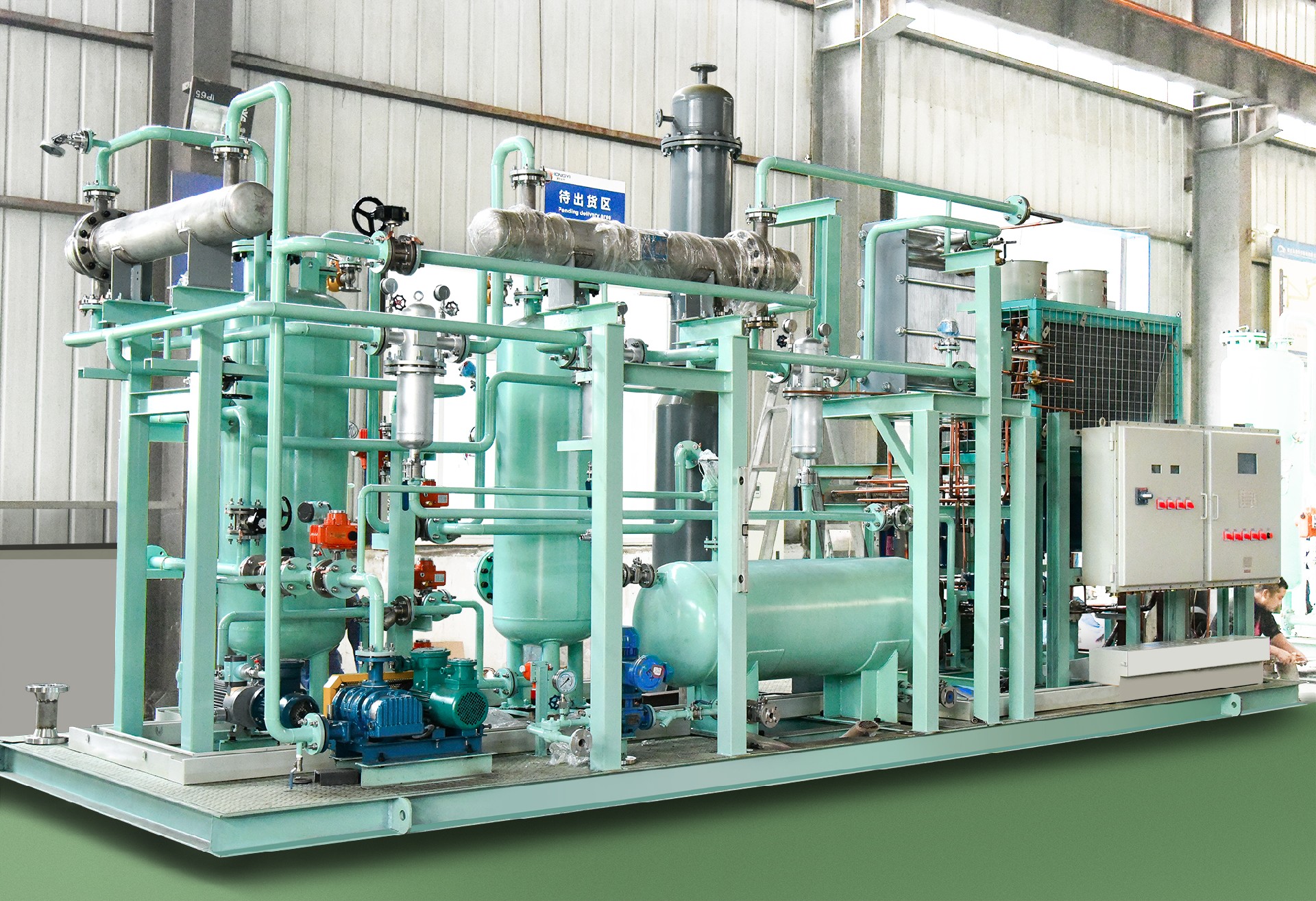 Process flow:The loaded oil and gas will enter the absorption tower from the air outlet of the tank car airtight cover through the external network pipeline under the effect of slight positive pressure, and contact the special absorbent sprayed from the top of the tower in the packing layer of the absorption tower. The absorbent selects hydrocarbon oil and gas. Absorption to realize the separation of hydrocarbons and air in the loaded oil and gas,The gas that is not absorbed by the absorbent is discharged through the flame arrestor.The absorbent enters the vacuum desorption tank under the action of the pressure difference, and the absorbed oil and gas are desorbed under vacuum conditions, and the absorbent is regenerated in the vacuum desorption tank.The desorbed oil and gas are transported to the absorption tower by the vacuum unit, and then transported to the product oil storage tank after being fully absorbed by the product oil to realize the oil and gas recovery. The unabsorbed oil and gas in the reabsorption tower returns to the absorption tower from the top of the regeneration tower and is absorbed by the absorbent again.
The problem can be seen from the calibration conclusion of the device. The recovery rate of the device is calibrated to 95.63%, and the monitored exhaust gas emission concentration is 5.88g/m3, and the back-calculated oil and gas inlet concentration is 134.55g/m3. This issue was raised to the other party at the meeting. , Interpreted as the result of winter measurement. This value is obviously low. After analysis, it is believed that there are several possibilities: 1. The problem of the measurement method; 2. The problem of the closed collection of oil and gas; 3. The random fabrication.
Since the absorption process is the absorption of all the oil and gas, the scale of the absorption tower is very large and will require a lot of space. The adsorption method only absorbs the gas generated during the regeneration process, and the gas volume is small.
From the perspective of the process, according to the principle of gas-liquid balance, the absorbent will continue to be consumed and needs to be replenished continuously.
3. Membrane separation method for oil vapor recovery unit
Gas membrane separation technology is a new type of gas separation technology based on the mechanism of dissolution and diffusion. The driving force of its separation is the partial pressure difference between the gas components on both sides of the membrane, and the difference in the permeation rate of the gas components when they pass through the membrane For gas separation. The organic vapor separation membrane is controlled by dissolution selectivity, the solubility of organic vapor in the membrane is large, and the permeation rate is fast, so as to realize the separation from small molecules.
The oil and gas mixture is first pressurized by a liquid ring compressor to 3.5 bar and enters the absorption tower, and the oil and gas after being absorbed by the light oil enters the membrane separation system. The VOC concentration in the gas on the trap side of the VOC-rich permeate gas flow membrane can reach 5-10g/m3.
Process flow:The oil-gas mixture is first compressed by a liquid ring. In order to improve the efficiency of the membrane separation system, a liquid ring vacuum pump is used to provide a vacuum of about 150 mbar in the permeation of the membrane.The permeate gas rich in VOC returns to the inlet of the liquid ring compressor.The VOC concentration in the gas on the interception side of the membrane can be reduced to 5-10g/m3, which can be directly discharged, or enter the grade PSA to reduce the VOC content in the discharged gas to 5mg/m3. The entire system guarantees a VOC recovery rate of over 99%.
4. Condensation oil vapor recovery unit
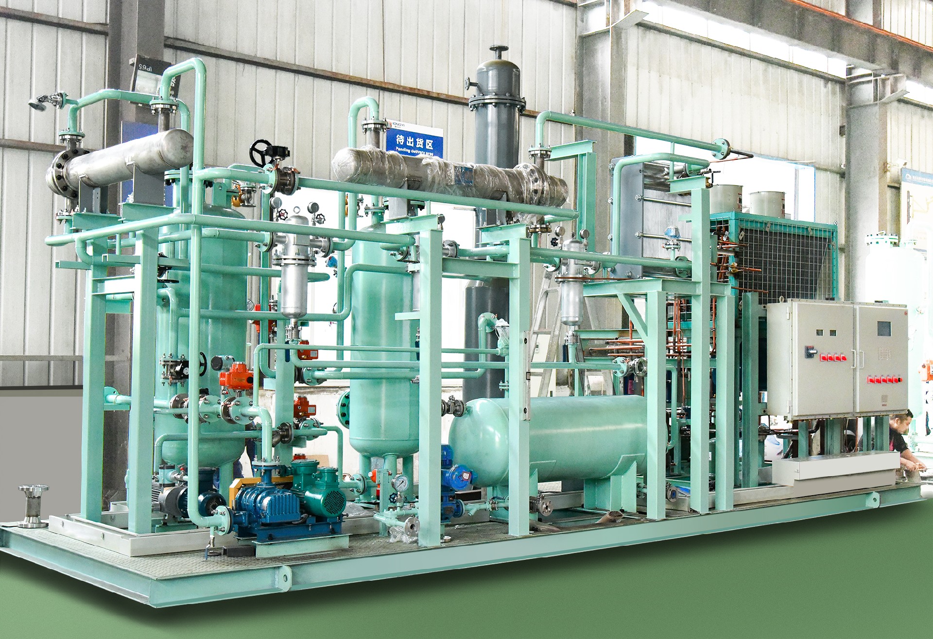
The technical principle of the oil and gas condensing process is to use the refrigeration engineering method to replace the heat of the oil and gas, so that the temperature of the various components of the oil and gas is lower than the freezing point from gaseous to liquid, so as to realize recycling.
It adopts multi-stage continuous cooling method to cool to -73℃, and the typical oil and gas recovery rate is 90-95%. It is condensed to -95℃, and the non-methane total hydrocarbon concentration of the outlet gas is ≤35g/m3.
The advantages of the condensation method of oil vapor recovery unit are simple process and good performance, and the recovered products are directly oil products.The pure condensing method oil-gas recovery device developed by the single-compressor self-cascade refrigeration technology can reduce the oil-gas temperature to -100℃~-120℃. The power consumption of the device in normal working condition is only 0.2(Kw·h)/m3 of oil and gas, and the electricity consumption is the same as that of the activated carbon adsorption method.
Condensing oil and gas recovery equipment has mature key technologies, relatively low cost, small floor space, easy maintenance, low operating costs, and only consumes electricity and cooling water (air cooling can also be used), and the recovery benefit is far greater than the energy expenditure. The processing capacity of pure condensing oil and gas recovery equipment is 5~500m3/h.
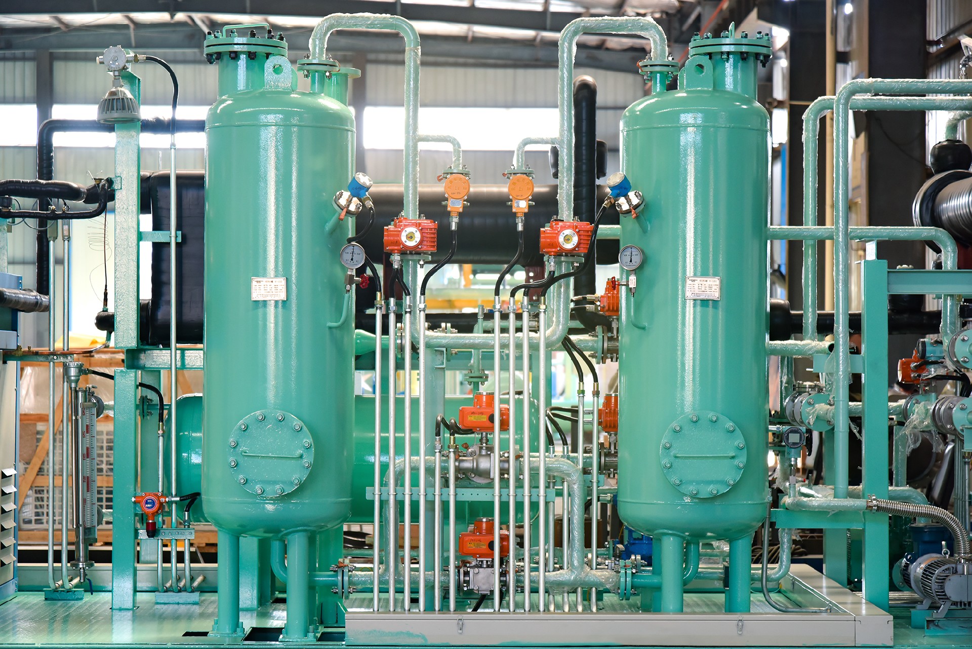 Process flow:The oil and gas are cooled in three stages and the temperature is reduced to below -100°C, thereby condensing clean hydrocarbon liquid.The temperature of the oil and gas is first reduced to 3 to 5°C, which condenses the hydrocarbons and the water carried in the air, reducing the possibility of frosting in the later stages.In refrigeration, the oil and gas are further cooled to -50~-65℃, and then cooled to -100~-110℃ through the third stage of refrigeration. The clean cold air condensed from the tertiary refrigeration is heated to 10°C or higher. The heat source comes from the heat recovery in the refrigeration system.Defrosting: The water vapor carried in the air entering the device will condense into liquid in the stage, and the remaining water vapor will frost in the stage. Foreign condensing oil vapor recovery unit are designed to preheat the defrosting liquid by the waste heat of the circulating refrigeration system. When the system is running continuously for 24 hours, two oil and gas condensers are required, one of which is defrosted, and the other will continue to run, and the system will automatically defrost and switch. The pure condensing oil vapor recovery unit is designed with a fast defrosting system, and the defrosting is completed within 3 to 5 minutes.
 Performance and index
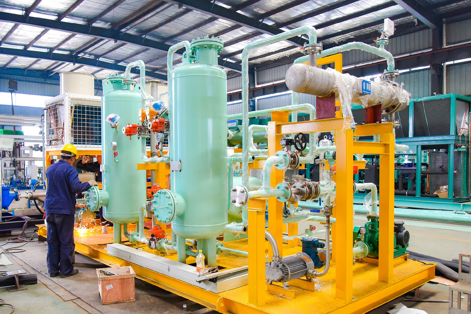
All components are Ex explosion-proof components; oil and gas channels have no mechanical or electrical components.Emission concentration-gasoline and naphtha, the exhaust gas outlet concentration reaches 12g/m3 (standard GB20952-2007 stipulates: oil and gas emissions reach ≤25g/m3).Load-operating when the design flow exceeds 150% to 180%, the recovery rate will drop slightly when overloading, and the gasoline recovery rate will be 90% when the design flow exceeds 150%.

 EN
EN
 RU
RU


